Our company has 18+ years of experience !
-
Monday- Saturday
09.00 AM to 06.00 PM -
Length
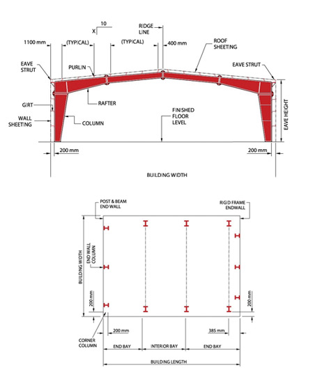
Building length is the distance between the outside flanges of endwall columns in opposite endwalls. It is a combination of several bay lengths.
Width
No matter what primary system is used, the building width is defined as the distance from outside of eave strut of one sidewall to outside of eave strut of the opposite sidewall.
Height
Building height is the eave height, which is usually the distance from the bottom of the main frame column base plate to the top outer point of the eave strut. When the columns are recessed or elevated from the finished floor, eave height is the distance from the finished floor level to the top of the eave strut.
Roof Slope: (X/10)
This is the angle of the roof with respect to the horizontal. The most common roof slopes are 0.5/10 and 1/10. Any practical roof slope is possible in PEB.
Bay Spacing (Interior Bay Length)
This is the distance between the center lines of two adjacent interior main frame columns. The most common bay lengths are 6m to 7.5m. Any bay length is possible up to 15 meters.
End Bay Length
This is the distance from the outside of the outer flange of end wall columns to the center line of the first interior frame column.
Sidewall & Endwall Conditions
This is about the wall cladding arrangements. Either it can be partially Brick wall and above steel cladding, or fully sheeted or fully brick wall.
Design of Structures
Our design department is fully supported by well qualified & experienced engineers duly backed up by two design consultants who are well known for their design skills inland & overseas. Detailed engineering design with data sheet of calculation will be submitted considering wind, dead, live load as per IS-875, & relevant coefficients for terrain category for the height of structure to determine the safe life of the building.
Design & Engineering Software Support
Staad Pro, MBS, Autocadd
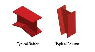
High grade steel plate conforming to ASTM A 572 M Grade 345 and IS 2062. Factory painted with the minimum of 35 Microns (DFT) of corrosion protection primer.
Design Loads Considered by Us (Standard)
Unless otherwise specified, Sathyam's Pre-Engineered Buildings are designed for the following minimum loads.
Roof live load: 0.57 Kn/m2 ( As per MBMA).
Roof live load: 0.57 Kn/m2 ( As per MBMA)
Design Wind speed: Upto 50m/sec (180 kmph)
(As per IS 875-1987)
International Quality Standards
LOW RISE BUILDING SYSTEMS MANUAL
Metal Building Manufacturers Association (MBMA)
ALLOWABLE STRESS DESIGN
American Institute of Steel Construction (AISC)
STRUCTURAL WELDING CODE
American Welding Society (AWS)
COLD FORMED STEEL DESIGN MANUAL
American Iron & Steel Institute (AISI)
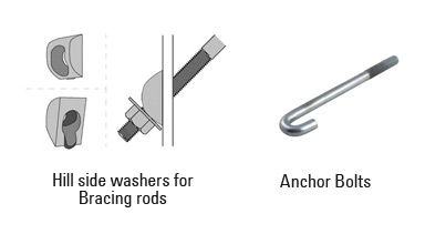
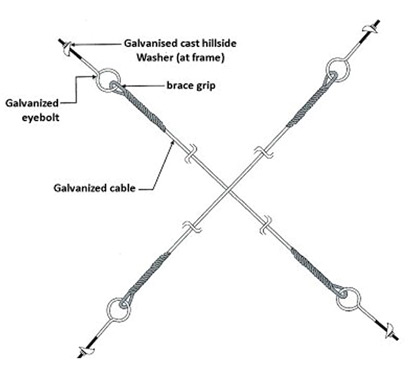
Bracings
